
Building a pneumatically actuated mechanical iris, Part 1
Background & early design validation

For the past few months, I’ve been working on a pneumatically actuated mechanical iris. This was pretty challenging - as I told a friend, it was by far the most complex mechanical device I’ve ever designed. Given the complexity, and the interest I’ve gotten from people, I thought it’d be worth documenting how it came to be. Over the next few weeks I’ll be telling the story of its creation, starting here with the background and design.
Always show the end result first though, right?
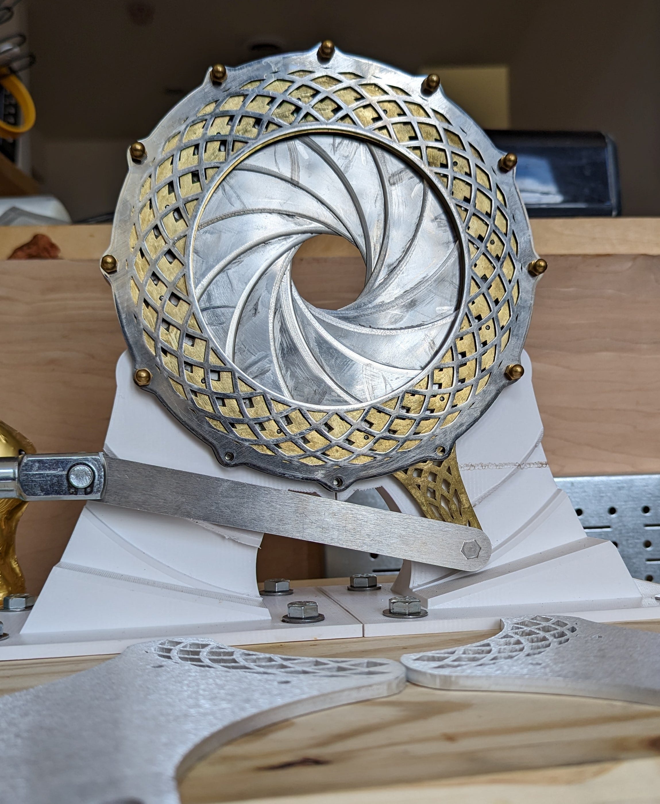
So there it is - a mechanical iris that actuates via a pneumatic cylinder and crank-slider linkage. A pair of switches control the device, one controlling a 5-way solenoid valve to set the piston in or out, and the other for a normally-closed 2 port solenoid that controls pressure to the 5-way. Power for the valves (and the switch lights) is provided by an 18v power tool battery stepped down to 12v through an automotive buck converter, and pressure is provided by a small air compressor.
But why, though?
A natural question. It’s a pretty crazy object to build for quite a ridiculous purpose. Philosophically, I think of art and enjoyment as leaf nodes in the great tree of Whys. The compiler helps build the CAD software, and the CAD software helps design a drill, and the drill helps drive a screw, and the screw helps hold together a house, and the house shelters us from the elements, all so that we can… enjoy life? If we enjoy something, that seems like reason enough to do it; the but-why stops there.
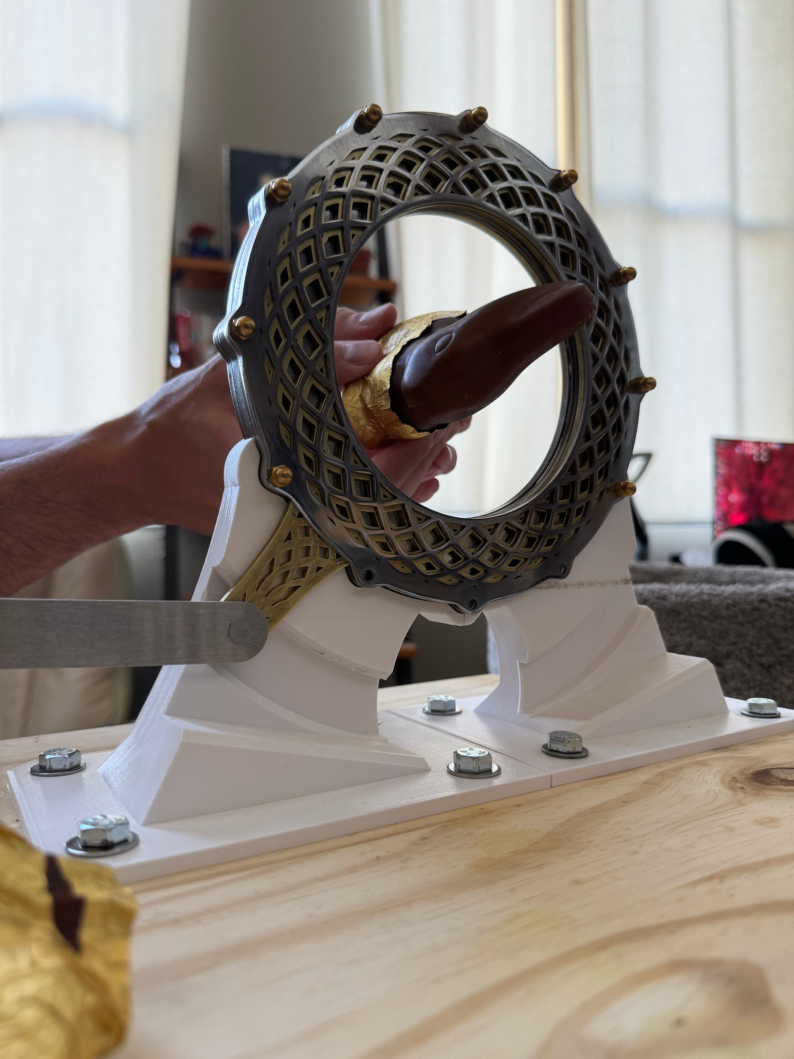
More concretely, for the past decade and more, my friend has hosted an annual Easter party, where hollow chocolate bunnies are decapitated and used as drinking vessels. Naturally, this started in college and has some prosaic explanation about care packages from home, a severe lack of cups & intolerably low BAC, etc, but as with all good traditions, it’s taken on a life of its own and now exists more for its own sake than any real explainable “reason”. It’s fun. No further explanation required, really.
As we’ve gotten older, the focus of the party has become less and less the drinking, and more and more the ridiculous devices for the decapitation of the bunnies. Early events had a simple-yet-iconic gravity-powered guillotine made by the host and his roommate, but later ones encouraged people to bring their own decapitators. There have been literal mousetrap-powered contraptions, electrically-heated resistance-wire garottes, and other such contrivances. In 2022, I brought a portable circular saw, and in 2023, a large bread knife heated red-hot by a propane torch. Both were fun, and provided a dramatic flair to the decapitation (the hot knife caused the chocolate to briefly catch fire while cutting), but relatively uncomplicated in design or execution.
For 2024, the host send a satirical “RFP” as the invite (we are nerds with an odd sense of humor), with a list of desiderata:

I knew what I wanted to do.
Mechanical irises are cool
I’ve thought that mechanical irises were extremely cool since long before I knew the phrase “mechanical iris”. In fact, I can pinpoint the origin of my interest in them with surprising accuracy, given the decades that have passed. It started with Star Wars, Episode V: The Empire Strikes Back.
Near the very end of the film, after Luke has heard the shocking news re:paternity, he ends up dangling from an antenna projecting off the bottom of Cloud City. Leia, newly attuned to the ways of the Force, realizes he’s in danger, and insists they return whence they just came (at great personal risk) to save him. She sends Lando back topside to catch Luke, and he has to open a series of narrow hatches in the Millenium Falcon’s hull to do so.
Fair use fair use please don’t hurt me Disney
As an adult, I now know that these are mechanical irises1, but as a kid, all I knew is that they were cool as hell. As usual with my design aesthetics, it seems it can be mostly blamed on the wizards at ILM.
When I read the “RFP” for the party, it crystallized some vague desire that had been floating in my head for years - I wanted to build a mechanical iris.
But how, though?
Turns out, mechanical irises are pretty complex devices. I’d had a vision for what I wanted to do, but achieving that vision would be a whole other challenge - I’d never even designed something with a non-rigid joint before. Step one would be doing the research to determine if this was at all feasible, given my capabilities and resources.
Searching around, I found a few interesting examples on YouTube, but they’re mostly of a type that aren’t suitable for cutting - window shutters, theater tech, etc. They use a style of blade that is only supported on one end, which allows complete or near-complete closure of the iris, but means that they’re loose at the “cutting edge” where the iris is closing.
After more searching, I eventually stumbled upon the amazing iris calculator blog and design tool, by Matt Arnold. It uses “banana style” blades which are supported on both ends, and the design tool makes it easy to specify a number of blades, desired min/max aperture sizes, etc, and then get a series of drawings which define the resulting blade and housing shapes.
An example of what the iris calculator gives you
I signed up for the free version immediately, and after playing with it for a while and building confidence that this could be exactly the starting point I needed, I gladly paid the nominal fee for the full version with unlocked parameters and dxf export.
Prototyping and validating the mechanical design
The calculator outputs drawings for several essential elements which define the motion of the iris
The blades: banana-shaped pieces which start nested inside the outer ring of the iris, and create the shrinking circle effect as they move. They require two pins projecting in opposite directions from the face of the blade – one up, one down.
The actuator ring: an annular shape with holes for the pins from the blades, which drives their motion.
The housing: A second annular shape, with linear slots for the other set of pins from the blades, which constrains their motion.
These outputs were a great starting point, defining outlines for some key elements, but they are still just a starting point. The 2D .dxf drawings specify shapes and their alignment, but have nothing to say about how to create an actual 3D object. For that, I turned to my CAD package of choice, Autodesk’s Fusion2.
Fusion is quite a complicated piece of software, with a plethora of features covering the design and manufacturing space - everything from CSG design to FEA simulation to photorealistic raytraced rendering to CNC toolpath generation. After six-plus years of use, I still often feel like I’ve only scratched the surface. For modelling the iris movement, I knew I’d have to learn about a feature I’d never really used before – joints.
Joints?
Joints. Joints are a foundational concept in mechanism design - maybe the foundational concept. Whenever an object includes motion between its pieces, that motion is modeled as a joint. In short, joints define constraints on the relative motion of sub-components of the overall assembly. A simple and familiar example is a wheel rotating around an axle – the wheel inherits five of the six degrees of freedom3 from the axle, while being able to rotate freely around the final axis.
The most common joints are the revolute (rotation around a single axis, like a wheel) and the slider (movement along a single axis, like a piston), but there are more, including:
Ball4: rotation in all three axes, with no positional movement
Rigid: no motion or rotation
Pin-slot: movement along one axis, and rotation around a second axis,
et cetera.
The motion of the iris blades is defined by three key joints:
A revolute joint from one of a blade’s pins to a matching hole in the actuator ring
A pin-slot joint from the other blade pin to a slot in the housing, and
A revolute joint from the housing to the actuator ring
The end result of these three joints is an actuator ring that can rotate relative to the housing, pulling one end of the banana blade along with it, while the other end of the banana blade slides along the pin-slot. This motion (repeated for each of the blades) gives rise to the shrinking-circle iris effect, as the blades move out from the ring and swing in towards the center.
By taking the drawings from the iris calculator and extruding them to create solid flat pieces, then applying the necessary joints, I was able to validate that the motion and linkage from the iris calculator should work, and that I would be able to make design updates within the CAD environment while still correctly modelling the behavior.
The first working prototype of the design and motion
At this point, I had the validation I needed that this crazy idea could actually work, and it could actually be executed by me. There was still a long (looong) way to go from a motion prototype in CAD to a functional device in the real world, but the unknown technical risks were mostly sorted. Now it would merely be a matter of actually designing the actual object, and actually building it. No big deal!
Stay tuned for more detail on the design and fabrication process of the real iris components, an introduction to pneumatics, an endless parade of 3D printer problems, and more!
Probably just a single prop, reused several times – gotta get as much mileage out of the build as you can, after all.
Formerly known as Fusion 360; clearly someone must have told them to “drop the ‘360’ – it’s cleaner that way”.
Positional (x, y, z), and rotational (x, y)
Sometimes known as “ball and socket” joints in other contexts
Incredibly clean cut!